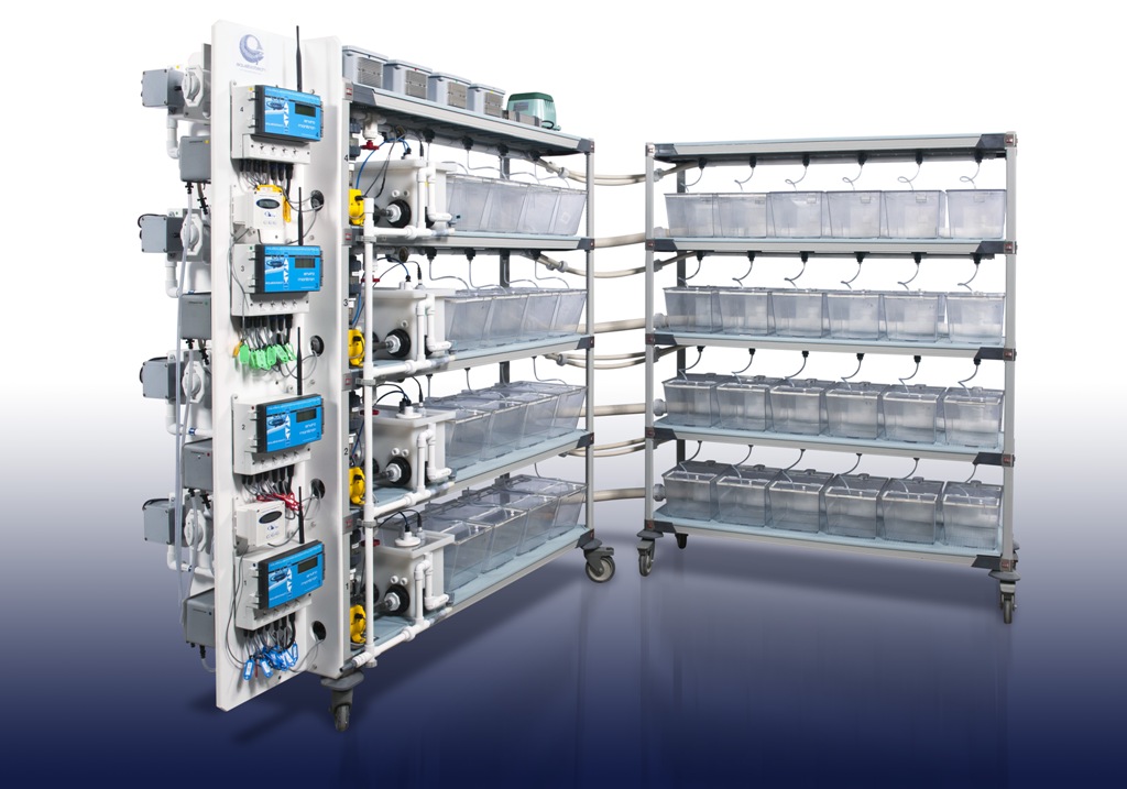
University of Saskatchewan – Multi-Stress System
University of Saskatchewan – Multi-Stress System
University of Saskatchewan – Multi-Stress System
The Hypoxic Unit is research unit consisting of four independent re-circulating systems. Each system consists of an Aeration Module (pump, aeration/gas mixing tower, gas control system) and a Habitat Module (sump-pump, water distribution line, rearing tanks & plumbing). Each system accommodates ten 9 Liter tanks
This unit is designed as a semi-open circuit assembly. This means that it is not equipped with a biological filter which would remove nitrogenous/ammoniacal products given off by aquatic organisms. The daily replenishment of make-up water must therefore exceed 164% of the total volume of the unit.
University of Saskatchewan – Multi-Stress System : Flow circulation
The water flow through the unit is divided into two pressure-fed circuits.
First Circuit (habitat module):
From the sump tank, the water is pumped through the screen filter, the flow regulating valve, along the water distribution header line, and passes through each water inlet valve into the rearing tanks. The effluent from each of the rearing tanks flows along a gutter and then returns by gravity into the sump tank.
Second Circuit (aeration module):
From the sump tank, the water is pumped to the gas mixing tower from where it returns by gravity to the sump.
A peristaltic-type pump allows the quantity of fresh make-up water to be precisely regulated. This pump is controlled by the Enviro-Monitron. The Enviro-Monitron is designed to control the replacement of 164% per day of the total volume of water in the unit. The displaced water (as effluent) is removed from the unit by means of the overflow standpipe located in the sump tank.
The water flow through the unit is divided into two pressure-fed circuits.
University of Saskatchewan – Multi-Stress System : Dissolved gases
Control of nitrogen concentration
The Gas degassing tower is designed to prevent nitrogen gas super saturation. Gas super saturation is a major cause of gas bladder problems and, in worst cases, fish kills in closed systems operating under pressure. Nitrogen (N2) supersaturation is caused by air leaks, pump cavitation, or rapid increase in water temperature. To provide protection from the accidental build-up of N2 gas, our gas mixing tower have a built-in low pressure section that provides constant degassing and aeration of all the water before it reaches the rearing tanks.
Control of carbon dioxide concentration
The design of the gas mixing tower makes it efficient at both CO2 degassing and oxygenation. The high air-to-water ratio and large contact area within the gas mixing tower maintain the CO2 level below 15 mg/L and the water well oxygenated. At high biomass loads, high-flow low-pressure air from the blower is injected into the gas mixing tower. The blower sends the air flowing up the tower counter-current to the water flow. This air exits by means of a chimney at the top of the gas mixing tower.
Control of oxygen concentration
The degassing tower oxygen control system allows precise control of the oxygen concentration in water. The concentration can be measured either in mg/L (minimum of mg / L) or in percentage of saturation. The oxygen control system consists of an oxygen sensor, the Enviro-Monitron, the gas mixing tower and an oxygen control box. The oxygen control box contains three micro-solenoid valves for high-precision gas-injection control (+ 0.1 mg / L). Each of these micro-valves allows for the injection of a specific gas; one for air, another for oxygen and the third for nitrogen. Depending on the oxygen set-point (measured in mg/L or % saturation), the Enviro-Monitron injects the gas mixture in the required proportions. It should be noted that the position of the air inlet valve of the blower must be set to recycle gas injected, that is the hypoxic position — which means that air is entering from the gas mixing tower and not from the ambient air.
An air compressor located on the top shelf of the unit allows air bubbles directly into the sump via an aeration stone. The air regulating valve is installed at the rear of the sump. This bubbling air should not be functional in an experiment under hypoxic conditions.


